| title | date | tags | |
|---|---|---|---|
软光栅器MicroRenderer(一) 渲染管线与三角形 |
2022-05-24 09:52:48 -0700 |
|
代码见:https://github.com/LJHG/MicroRenderer
最近仿照了这位大佬的博客软渲染器Soft Renderer:3D数学篇 | YangWC's Blog来实现一个软光栅器,其中的代码结构基本上参照了它的代码,一边参考一遍自己写把渲染管线实现了一下,在这里稍微记录一下。
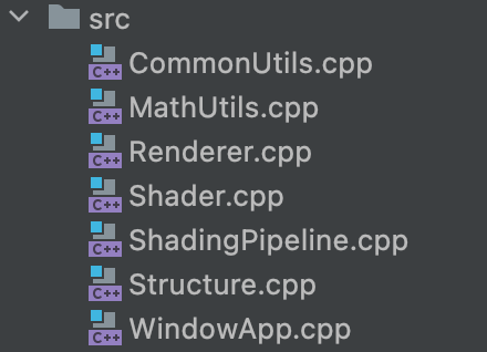
目前基本的代码结构是这样的:
这里大致说一下每一个文件的作用(虽然后续有重构的可能性):
- CommonUtils.cpp。用来存放一些通用函数,比如说读取图片之类的。
- MathUtils.cpp。用来存放数学相关的函数,比如说计算MVP矩阵,插值等。
- Renderer.cpp。渲染相关代码,用来管理渲染的物体以及调用渲染管线渲染等。
- Shader.cpp。存放shader代码。
- ShadingPipeline.cpp。渲染管线代码,生成渲染结果。
- Structure.cpp。定义vetex, frament 以及 mesh的数据类型。
- WindowApp.cpp。SDL2相关函数。
关于Renderer 和ShadingPipeline 以及 Shader 的组织问题:
关于这三个类的所属关系大概是:
ShadingPipeline 是 Renderer的一个成员,同时 Shader 是 Shadingpipeline的一个成员。
Renderer主要负责管理场景里的Mesh,同时调用Shadingpipeline去渲染。
ShadingPipeline主要负责渲染管线的一整套流程,比如说根据vertices indices 构建三角形,比如说光栅化。
Shader主要负责实现自己的vertexShader以及FragmentShader函数。
基本上可以把渲染的整个过程抽离为 生成像素buffer -> 显示像素buffer。显示像素buffer这个部分就交给了SDL2来做,只需要在每一帧的时候把一个像素数组传递给SDL2就可以展示了,所以我们的渲染器所需要的就是在每一帧生成出这个像素数组就可以了。这里的选取是非常随意的,在GAMES101里使用的opencv来把结果存成图片,这位大佬的博客使用了qt来展示结果,后来他后续把代码重构了,也是使用的SDL2。
比如说其实核心就是 updateCanvas这个函数:
void WindowApp::updateCanvas(uint8_t* pixels, int width, int height, int channel) {
    SDL_LockSurface(windowSurface);
    Uint32* surfacePixels = (Uint32*)windowSurface->pixels; //获取当前屏幕的像素指针
    for(int i=0;i<height;i++){
        for(int j=0;j<width;j++){
            int index = i*width + j;
            Uint32 _color = SDL_MapRGB(
                    windowSurface->format,
                    pixels[index * channel + 0],
                    pixels[index * channel + 1],
                    pixels[index * channel + 2]);
            surfacePixels[index] = _color;
        }
    }
    SDL_UnlockSurface(windowSurface);
    SDL_UpdateWindowSurface(window);
}
通过每次传入一个pixels矩阵就可以实现画面的更新了。
shader的设计大概是这样的:
class Shader {
public:
    virtual VertexOutData vertexShader(VertexData& v)  {VertexOutData _v; return _v;}; //meaningless implementation
    virtual glm::vec4 fragmentShader(VertexOutData& v) {glm::vec4 r; return r;}; //meaningless implementation
    void setModelMatrix(glm::mat4 matrix);
    void setViewMatrix(glm::mat4 matrix);
    void setProjectionMatrix(glm::mat4 matrix);
private:
    glm::mat4 modelMatrix;
    glm::mat4 viewMatrix;
    glm::mat4 projectionMatrix;
};

class SimpleShader: public Shader{
public:
    VertexOutData vertexShader(VertexData &v) override;
    glm::vec4 fragmentShader(VertexOutData &v) override;
};
如果要实现一个shader,比如说phong shader, 那么就去继承基类Shader,然后实现它的虚函数vertexShader以及 fragmentShader。一般来说,vertexShader里要做的事就是实现mvp变换, fragmentShader要做的事就是对于一个像素,给出它的颜色(这里也不完全是,但是对于这里的最简单的SIMPLE_SHADER是这样的)。
在这里重温一下渲染管线:
首先传入vertex data, 经过vertex shader后会得到一个新的数据,里面会包括经过坐标变换后的坐标,再经过了视图变换(我不是很清楚视图变换是否应该写在vertex shader里)过后就可以进行光栅化了。在进行光栅化的过程中,我们需要决定每一个像素应该给什么颜色,所以就需要使用插值来插值出那个像素点的世界坐标,纹理坐标等数据,然后把它传给fragment shader,最后得到颜色。
这里要说的是,我这里写的代码fragment shader的输入数据是VertextOut,这个数据类型是vextex shader输出的数据类型。通过对不同VertextOut进行差值,我们可以得到一个新的VertextOut来作为结果给fragment shader,所以好像也没毛病。。。
这里展示一下渲染管线的代码:
void ShadingPipeline::shade(const std::vector<VertexData>& _vertices,
                                const std::vector<unsigned int>& _indices,
                                int rasterizingMode) {
        //according to indices, every 3 indices organize as a triangle, len(indices) could be greater than len(_vertices)

        VertexData v1,v2,v3;
        VertexOutData v1o,v2o,v3o;
        for(int i=0;i<_indices.size()/3;i++){
            v1 = _vertices[_indices[i*3+0]];
            v2 = _vertices[_indices[i*3+1]];
            v3 = _vertices[_indices[i*3+2]];
            //vertex shader
            v1o = shader->vertexShader(v1);
            v2o = shader->vertexShader(v2);
            v3o = shader->vertexShader(v3);

            //view port transformation
            v1o.position = viewPortMatrix * v1o.position;
            v2o.position = viewPortMatrix * v2o.position;
            v3o.position = viewPortMatrix * v3o.position;

            //rasterization
            // the triangle will appear upside down because it goes like ➡️ x ⬇️ y, but never mind...
            if(rasterizingMode == LINE){
                // BresenHam line drawing algorithm
                bresenhamLineRasterization(v1o,v2o);
                bresenhamLineRasterization(v1o,v3o);
                bresenhamLineRasterization(v3o,v2o);
            }else if(rasterizingMode == FILL){
                // bounding box inside triangle fill algorithm -> games101 assignment2 and assignment3
                fillRasterization(v1o,v2o,v3o);
            }

            // double buffer
            swapBuffer();
        }
   }
因为这里是直接画三角形,我的vertex shader里直接传递数据,同时fragment shader也是直接传递颜色。所以我传的vertex data就是直接的ndc坐标,经过视图变化过后得到像素坐标,然后就可以进行光栅化了。
其中,填充的光栅化算法长这样:
void ShadingPipeline::fillRasterization(VertexOutData &v1, VertexOutData &v2, VertexOutData &v3) {
   // I don't know name for this algorithm
   // ref: GAMES101 assignment2: https://www.ljhblog.top/CG/GAMES101/assignment2.html
   float x1 = v1.position[0]; float y1 = v1.position[1]; float z1 = v1.position[2];
   float x2 = v2.position[0]; float y2 = v2.position[1]; float z2 = v2.position[2];
   float x3 = v3.position[0]; float y3 = v3.position[1]; float z3 = v3.position[2];

   // get bounding box of the triangle
   int left = static_cast<int>(std::min(std::min(x1,x2),x3));
   int bottom = static_cast<int>(std::min(std::min(y1,y2),y3));
   int right = static_cast<int>(std::max(std::max(x1,x2),x3)) + 1; //ceil
   int top = static_cast<int>(std::max(std::max(y1,y2),y3)) + 1; //ceil

   for(int x = left;x<=right;x++){
       for(int y=bottom;y<=top;y++){
           if(MathUtils::insideTriangle(static_cast<float>(x),static_cast<float>(y),x1,y1,x2,y2,x3,y3)){
               VertexOutData tmp = MathUtils::barycentricLerp(x,y,v1,v2,v3);
               int index = y*width+x;
               if(tmp.position[2] < zBuffer[index]){
                   zBuffer[index] = tmp.position[2];
                   //fragment shader
                   glm::vec4 color = shader->fragmentShader(tmp);
                   int colorIndex =  index*3; //multiply channel
                   imageSwap[colorIndex +0] = static_cast<int>(color[0]);
                   imageSwap[colorIndex +1] = static_cast<int>(color[1]);
                   imageSwap[colorIndex +2] = static_cast<int>(color[2]);
               }
           }

       }
   }
}
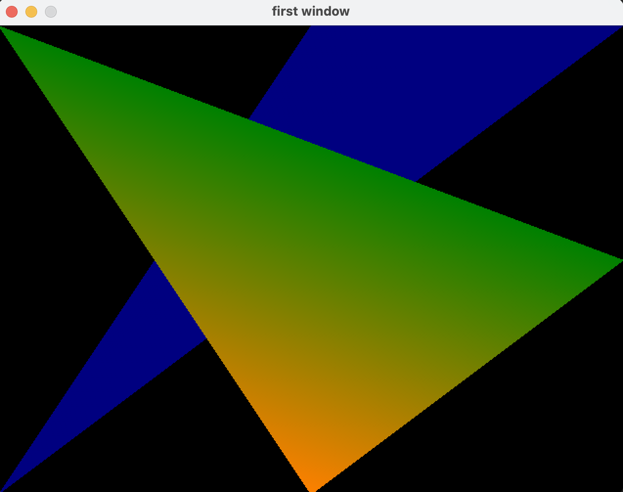
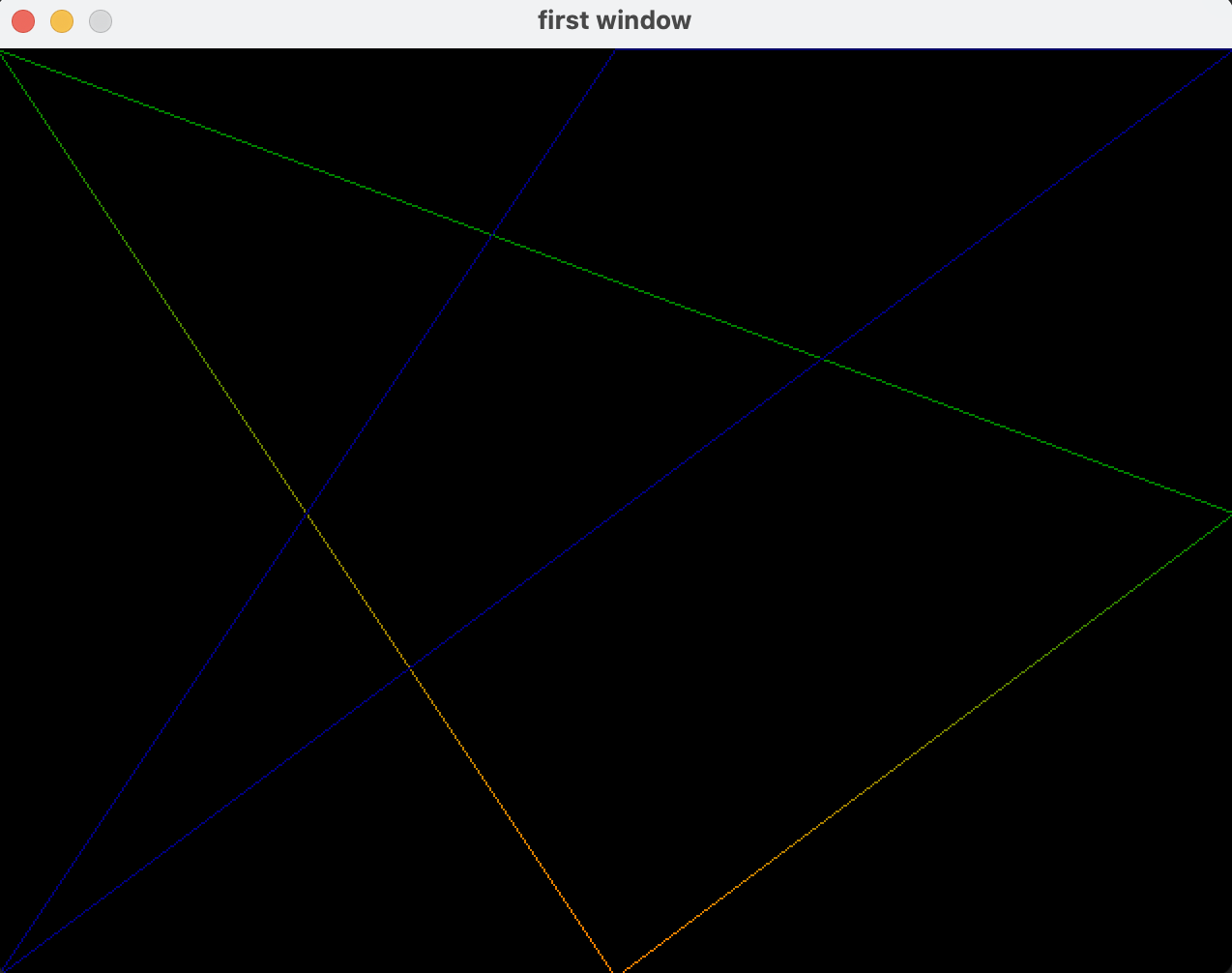
最后得到的结果大概长这样:


