-
Notifications
You must be signed in to change notification settings - Fork 129
NetFPGA 1G Ported Switch 10G
ported_switch_10g
contrib-projects/ported_switch_10g
- NetFPGA-10G Specific cores
- Xilinx AXI Peripheral
- Microblaze Subsystem
- Contribution
- Other
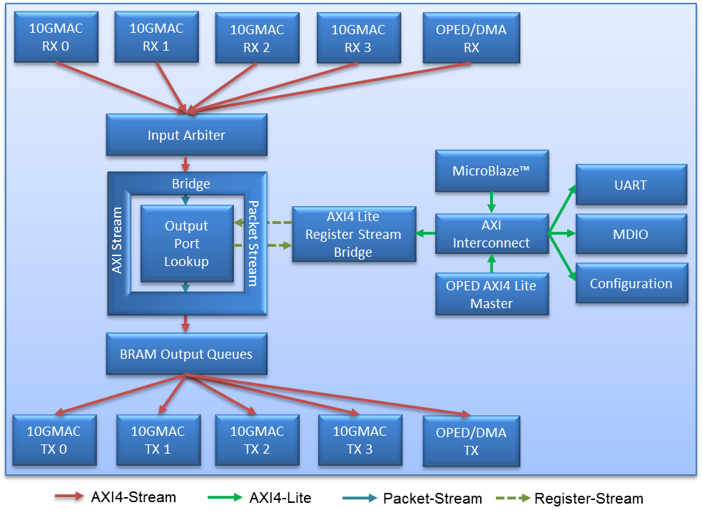
This section describes the mechanism for integrating existing 1G Output Port Lookup modules into the 10G pipeline. This has been achieved using two newly developed IP cores namely, AXI4-Stream to Packet Bus Bridge and AX4-Lite to Register Bus Bridge. Remainder of the section is on how to use these two bridges in a 10G design. For information on rest of the reference pipeline, visit NetFPGA 10G Reference NIC 1G.
These two libraries are tested using Output Port Lookup Modules (OPL) taken from NetFPGA-1G core library e.g. NIC and Learning CAM Switch. Here we provide a general guideline that will help in setting up the library.
Before starting the porting process, the NetFPGA-1G OPL module is wrapped in an EDK compliant peripheral core. This can be done using the provided sample template which contains a generic top exposing necessary Packet Bus and Register Bus interfaces. Once done, this core is integrated into the 10G desgin using the bridges.
-
Inserting AXI4-Stream and Packet Bus Bridge
- Insert the NetFPGA-1G core in the EDK project.
- Connect the M_PBS bus of the "AXI4-Stream to Packet Bus Bridge" to the S_PBS bus of the NetFPGA-1G core.
- Connect the S_PBS bus of the Bridge to the M_PBS bus of the NetFPGA-1G core.
- Connect the S_AXI bus of the Bridge to the preceding Master module in the design e.g. if you are porting an Output Port Lookup Module, you should connect it to the Input Arbiter.
- Conncet the M_AXI bus of the Bridge to the following Slave module in the design e.g. if you are porting an Output Port Lookup Module you should connect it to the BRAM Output Queues.
-
Inserting AXI4-Lite and Register Bus Bridge
- Connect the M_RBS bus of the "AXI4-Lite to Register Bus Bridge" to the S_RBS bus of the NetFPGA-1G core.
- Connect the S_RBS bus of the Bridge to the M_RBS bus of the NetFPGA-1G core.
- Connect the S_AXI bus of the Bridge to the axi_interconnect.
- In the Master/Slave specifc settings of the axi_interconnect, check the ACLK setting as asynchronous with respect to the Bridge.
In this section, we describe the process of porting the NetFPGA-1G learning CAM switch to the new 10G platform. The steps are:
-
Create a new EDK core for the NetFPGA-1G learning CAM switch library. Replace the black-box CAM with the Virtex5 compatible CAM using the XAPP1151.
-
Insert the AXI4-Lite to Register Bus Bridge in the EDK project. Doing so will set a default address range for this block e.g. 0x76c00000 to 0x76c0ffff.
-
Set the parameter C_RBS_RING_SIZE to 16.
-
Hardcode the switch parameters with the following values in the op_lut_regs.v module
- SWITCH_OP_LUT_REG_ADDR_WIDTH = 6
- SWITCH_OP_LUT_BLOCK_ADDR = 17'h0
- SWITCH_OP_LUT_PORTS_MAC_HI = 0 (axi address = 0x76c00000)
- SWITCH_OP_LUT_MAC_LO = 1 (axi address = 0x76c00004)
- SWITCH_OP_LUT_NUM_HITS = 2 (axi address = 0x76c00008)
- SWITCH_OP_LUT_NUM_MISSES = 3 (axi address = 0x76c0000c)
- SWITCH_OP_LUT_MAC_LUT_RD_ADDR = 4 (axi address = 0x76c00010)
- SWITCH_OP_LUT_MAC_LUT_WR_ADDR = 5 (axi address = 0x76c00014)
-
Connect the M_RBS bus of the "AXI4-Lite to Register Bus Bridge" to the S_RBS bus of the NetFPGA-1G core.
-
Connect the S_RBS bus of the Bridge to the M_RBS bus of the NetFPGA-1G core.
-
Connect the S_AXI bus of the Bridge to the axi_interconnect.
-
In the Master/Slave specifc settings of the axi_interconnect, check the ACLK setting as asynchronous with respect to the "AXI4-Lite to Register Bus Bridge".
-
Insert the "AXI4-Stream to Packet Bus Bridge" in the EDK project.
-
Connect the M_PBS bus of the "AXI4-Stream to Packet Bus Bridge" to the S_PBS bus of the NetFPGA-1G core.
-
Connect the S_PBS bus of the Bridge to the M_PBS bus of the NetFPGA-1G core.

After configuring the system as explained above, functional tests were performed in order to validate the system. For the Datapath, system operates as a Learning CAM Switch. The status registers are read and verified using the driver_ctrl utility provided with the NetFPGA-10G reference NIC 10G device driver.
It's worth noticing that using this porting mechanism, the obtained switch is faster than when ran on the existing NetFPGA-1G platform but is not fully 10G compatible.