-
Notifications
You must be signed in to change notification settings - Fork 190
Output circuits, filters, amplifiers, etc. (* this has content)
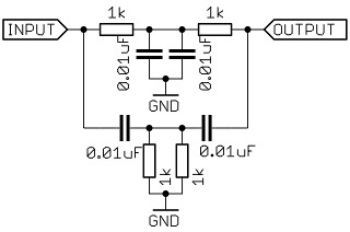
##Output circuit for HIFI mode Mozzi's HIFI audio mode combines the output of 2 pins in a technique called dual PWM, which is explained in detail at [Open Music Labs] (http://www.openmusiclabs.com/learning/digital/pwm-dac/dual-pwm-circuits/).
Here's the circuit for Mozzi, based on the Open Music Labs article.
####Advantages of HIFI mode
- Higher resolution sound than STANDARD mode.
- Doesn't need a notch filter on the audio signal because the carrier frequency is out of hearing range.
####Disadvantages
- Requires 2 pins, 2 resistors and a capacitor, so it's not so quick to set up compared to a rough, direct single-pin output in STANDARD mode.
####Pins and where to put the resistors on various boards for HIFI mode
Boards tested in HIFI mode have an x, though most of these have been tested in STANDARD mode
and there's no reason for them not to work in HIFI (unless the pin number is wrong or something).
Any reports are welcome.
resistor.....3.9k......1M
x................9..........10...............Arduino Uno
x................9..........10...............Arduino Duemilanove
x................9..........10...............Arduino Nano
..................9..........10...............Arduino Leonardo
x................9..........10...............Ardweeny
x................9..........10...............Boarduino
x................11.........12...............Freetronics EtherMega
.................11.........12...............Arduino Mega
.................14.........15...............Teensy
...............B5(14)...B6(15)...........Teensy2
x..............B5(25)...B6(26)...........Teensy2++
.................13.........12...............Sanguino
###Low pass audio filter Mozzi's sound output can be filtered to reduce aliasing at high frequencies. Here's some info about low pass RC filters and a calculator to help choose components. For Mozzi, an RC filter with a roll-off frequency of just under 6kHz works well, using a 270 Ω resistor and a 100n capacitor, as shown below. In HIFI mode, this would be on the combined audio output signal rather than straight from pin 9.
###Notch filter for STANDARD mode carrier frequency
This may still be useful if you need to use STANDARD mode for some reason, for instance if you need Timer 2 for another process. Otherwise HIFI mode is simpler and better.
The 16384 Hz pwm carrier frequency can also be uncomfortably audible for some people, depending on your hearing.
Here's a hearing test.
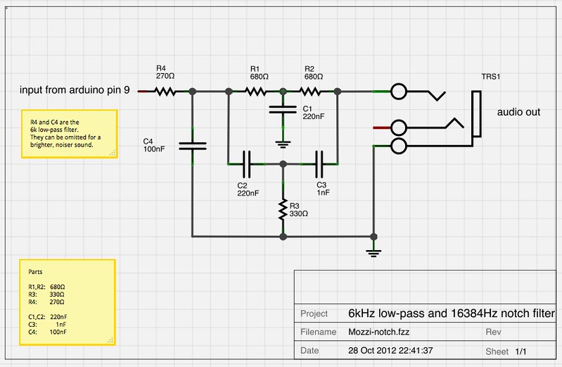
People who have used Mozzi with children report that kids find the carrier frequency particularly irritating, however adults are often unable to perceive it at any level! Many thanks to Andrew McPherson, who sent a schematic and equation for a twin-T notch filter which he used successfully to remove the offending frequency.

Here's a design tool for calculating Twin-T notch filters.
Andrew also reported that the low-pass and notch filter described here can be used together in series without any problems.
Here's a schematic for the 6kHz low pass and the notch filter using commonly available parts chosen to exactly match Mozzi's 16384Hz carrier frequency, using the notch filter design tool.
###Download Download a Fritzing file with breadboard, schematic and circuit board layouts here.
###Plots Below are plots of Mozzi playing white noise without filtering, with the notch filter, and with the low pass as well as the notch filter. You can see the 16kHz spike clearly - at about -7dB before filtering, -54dB after the notch alone (also notice the foldover frequencies above the spike), and -50dB with the addition of low pass before the notch. That's interesting! The spike is higher with the low pass! (though I couldn't hear it). It didn't occur to me to try the low pass after the notch. That might be better.
White noise, no hardware filter:
White noise after 16384 Hz notch filter:
White noise after 6kHz low pass and 16384 Hz notch filter:


