-
Notifications
You must be signed in to change notification settings - Fork 2
Install AM32
It is much easier to just purchase ESCs that already have AM32 installed. This repo's wiki has a page with a list of ESCs with AM32 already installed.
If you want to install AM32 on your own, the original instructions are from the official AM32 project: https://github.com/AlkaMotors/AM32-MultiRotor-ESC-firmware/wiki/Hacking-Guide . My instructions below is similar and is focused on the latest software version from ST.
AM32 firmware is firmware for brushless ESCs that are using 32-bit microcontrollers. It has a few advantages over other ESC firmwares, and it is completely open source. Because it is open source, it can be used with a lot of existing ESCs, and it can also be used when somebody wants to design an entirely new ESC.
There are a few ESCs sold with AM32 pre-installed, and with some hacking, people can also install AM32 on some ESCs that are already using BLHeli_32 firmware.
AM32 has two parts, the first part is the AM32 bootloader. The bootloader is what allows AM32 to update firmware later. Hydra firmware is written so that the AM32 bootloader can load Hydra firmware into ESCs. It is more convenient (and maybe cheaper) than other methods of installing Hydra firmware.
You will need:
- good soldering skills, a fine tip soldering iron, thin-ish solder and other soldering accessories.
- thin wire, something like 28 AWG or 30 AWG, and also be able to terminate them with a dupont-style female connector.
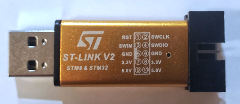
- ST-Link V2, which is a SWD programmer/debugger for STM32 microcontrollers
- STM32CubeProgrammer, which is software for the ST-Link
There are cheap places to buy a ST-Link

I wrote an entire guide on how to find the SWDIO and SWCLK signals (click here)
First, examine your ST-Link, we need to know where the three signal we need are.


Using a combination of wires and soldering, connect everything as shown:

I wrote an entire guide on how to find the SWDIO and SWCLK signals (click here)
You need to know what the microcontroller is on the ESC, and which signal input pin it uses, I wrote an entire guide on how (click here)
For STM32F051, download one of the two bootloaders here
For STM32G071, download this bootloader (64K version)
For AT32F421, go to this page and download either F421_PA2_BOOTLOADER_V2.hex or F421_PB4_BOOTLOADER_V2.hex depending on which signal input pin
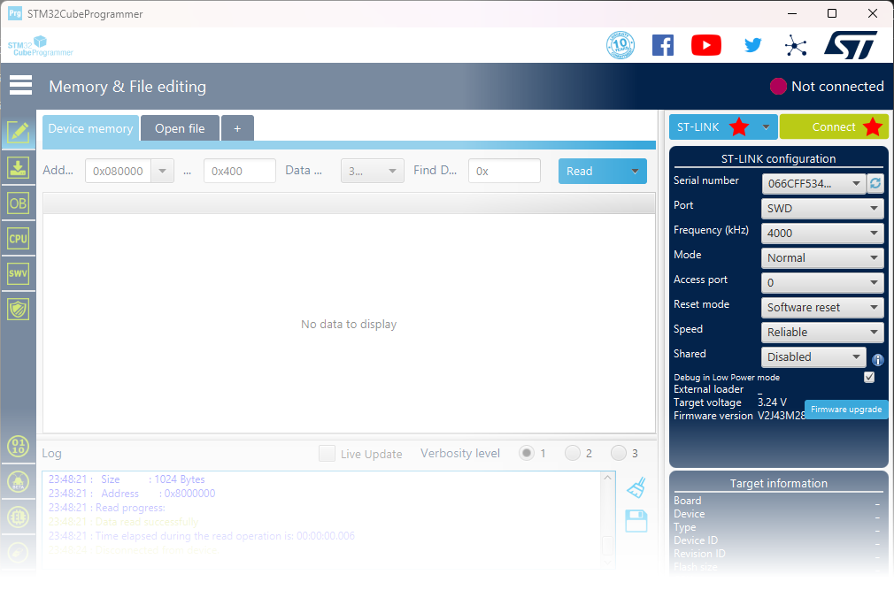
With everything connected, power on the ESC. Run STM32CubeProgrammer. Make sure that ST-Link is selected and then click Connect. (make sure the settings on the right side of the screen match what is shown in this screenshot)

Most likely, the chip will have security enabled, and the data cannot be read to prevent people from copying it. But you can at least see if you've got the right microcontroller connected.

WARNING: unlocking a BLHeli32's microcontroller causes the firmware to be erased forever, it cannot be undone, you cannot get it back, there's no way to make a backup, it is not available for download, you will be forced to use AM32 forever
If the ESC is using the STM32F051 microcontroller, follow these steps to unlock it:
Open the OB tab (option bytes), then open the Read Out Protection accordion, then change the RDP value to AA. Then click Apply. A confirmation will appear.

Confirm that you can read the chip now. It will be blank (all 0xFF data).

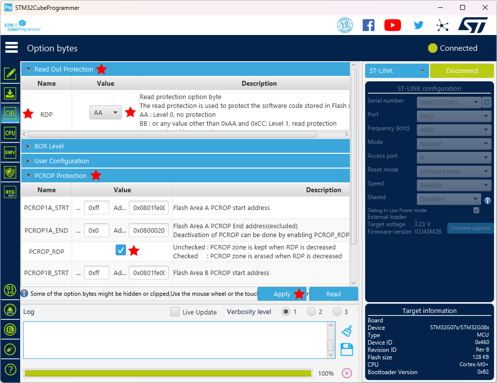
If the ESC is using the STM32G071 microcontroller, follow these steps to unlock it:
Open the OB tab (option bytes), then open the Read Out Protection accordion and the PCROP Protection accordion
Change the RDP value to AA. Make sure the PCROP_RDP checkbox is checked.
Then click Apply. A confirmation will appear.

Confirm that you can read the chip now. It will be blank (all 0xFF data).

If the ESC is using the STM32F051 microcontroller: Make sure all the settings checkboxes are checked (no protection whatsoever). Then click Apply.

If the ESC is using the STM32G071 microcontroller: Make sure the settings match the table below (if a setting is not mentioned, do not touch it). Then click Apply.
| Setting | Value |
|---|---|
| RDP | AA (no protection) |
| BOR_EN | unchecked (disabled) |
| BORR_LEV | 3 |
| BORF_LEV | 3 |
| nRST_STOP | checked (no reset) |
| nRST_STDBY | checked (no reset) |
| nRST_SHDW | checked (no reset) |
| IWDG_SW | checked (software) |
| IWDG_STOP | checked (active) |
| IWDG_STDBY | checked (active) |
| WWDG_SW | checked (software) |
| RAM_PARITY_CHECK | checked (disabled) |
| nBOOT_SEL | checked (use nBOOT0 bit) |
| nBOOT1 | checked |
| nBOOT0 | checked |
| NRST_MODE | 3 |
| IRHEN | checked |
| PCROP_RDP | unchecked |
| WRP1A_STRT | Value 0x3F, Address 0x0801F800 |
| WRP1A_END | Value 0x00, Address 0x08000000 |
| WRP1B_STRT | Value 0x3F, Address 0x0801F800 |
| WRP1B_END | Value 0x00, Address 0x08000000 |
| BOOT_LOCK | unchecked |
Critically, if you get any errors during chip-erase, it's probably because WRP1A_STRT, WRP1A_END, WRP1B_STRT, or WRP1B_END are set wrong.
Open the Download tab. Use the Browse button to select the bootloader file you have downloaded before. Set the Start Address to 0x8000000 (please do not get this wrong). Make sure Verify is checked.
Click Start Programming. The flashing process will start, and then you will get some confirmations.

You are done.
Next step is to install the Hydra firmware