-
Notifications
You must be signed in to change notification settings - Fork 2
Other Hardware Hacking
The Hydra firmware was written for the ESCs using STM32F051, STM32G071, and AT32F421 microcontrollers. The ESCs on the market vary a bit between different models and different manufactures, these are the main points that we are worried about:
- which pin is used for the main signal input
- there are two possibilities, PA2 or PB4, STM32G071 only uses PB4
- what kind of LED is on the circuit
- single-colour or RGB-capable
- is it preloaded with the AM32 bootloader
- how are the sensors calibrated
In the firmware release package, there are files marked as GENERIC that are also marked with the above variations. For example, the file named GENERIC_F051_PA2_RGBLED means it's compiled for a STM32F051 microcontroller that is using PA2 as the main signal input, and has a RGB LED on it.
If the AM32 bootloader is preloaded, then the Hydra firmware installer will display an error message if you attempt to install a firmware that does not use the same main signal input pin as the bootloader itself.
If the AM32 bootloader is not preloaded, then this is much more difficult, you can either:
- use a multimeter's continuity test to determine where on the actual chip the signal leads to, matching it against the STM32F051 datasheet
- just try different firmwares until it works
- check against AM32's database of known ESCs

You just need to look at the chip very closely. It will say F051K6 or G071GB or AT32F421 on there.
If you have a BLHeli_32 ESC, the easiest way to see what kind of LED you have is to just use the ESC for a bit and see if the LED changes colour.
NOTE: AM32 firmware does not actually use multiple colours even if the circuit has a RGB capable LED.
RGB LEDs are rather big, they have a very squarish rectangular shape...

...with a big circle, and 4 legs. Or, some of them look like this:

If the LED looks very small and not very complicated inside, then it is probably just single-colour.
You are free to try the RGB firmware on ESCs without a RGB LED, it won't cause damage. In fact, it might actually light up.
The best way to use Hydra firmware is to find the telemetry signal on the ESC. You can use it as the second RC PWM pulse input, or you can use it as the CRSF input.
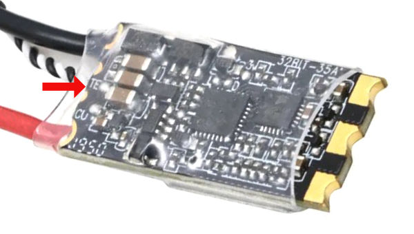
Sometimes it is the signal pad beside the main signal pad. It will be labelled as T ot TX or TE.


If you cannot find a telemetry signal, then you will need to find the SWD signal called SWCLK because SWCLK is capable of being a second signal input that can also handle CRSF input.
Also, if you do not have AM32 preloaded, you will need to find both SWDIO and SWCLK in order to install AM32.
First, understand where on the microcontroller these signals connect to:

Since they are in the corner, they make it really easy to identify on a ESC's circuit board. SWD signals usually come in a group of 4: SWCLK, SWDIO, power, and ground. And these signals are usually very close to the microcontroller. Typically, you will be able to visually see which pad corresponds with which signal.

This one is a bit harder but you can still at least see where SWDIO is connected, and then make an assumption about SWCLK.

Sometimes they are not in a group of 4, and sometimes they are labelled as C for SWCLK, and D for SWDIO

Here's another example, the SWC is hard to read, but you can read SWD and just assume the other one is SWC

To solder to these pads, thin 30 AWG wire is recommended, preferably with a kynar insulating jacket. Once soldered, it's a good idea to secure the delicate wire with glue.


I have moved the guide on this topic to a separate page, please click here
Please understand that not all ESCs have voltage sensing or current sensing. If one of these sensors is missing, it might read 0, it might also read crazy noisy values.
You need to do these calibrations in order to use the current limiting feature, and low-battery limiting feature.
I have moved the sensor calibration guide to a separate page, please click here